Rigid Blue: Potentiometer controlled RGB lights
|
Rigid Blue was created as a light control device for my recital.
by using a strip of 300 RGB LED's i intend to cotrol the colour of the environment around the audience. This project, like all the others, had its share of challenges. I wanted to create a device for my performace that would be controlled manually, and could run effectively without it being plugged into my laptop. So the plan was to power it using a DC power supply. I did a dive into a series of online forums and found a post where someone had calculated how much amperage was required for different amounts of Neopixel lights in series. With this discovery i knew that i would need to run 5V 2 Amps through my lights to run them at their full potential. I looked on Ebay and found DC power supplies galore, but they all costed around $35, $40. It felt expensive, what if i bought one of these power supplies and it just didnt work? I'd be out $40 and id have a useless power supply... I put the project aside for a few weeks, i was due to visit my parents soon and i knew my Dad would be able to help me either confirm this chart, or help me in some other way. When i visted, My Dad and I spoke about current and voltage, how voltage is similar to pressure in a hydraulic system, and amperage is like flow. I even managed to pick up 2 12V 2000mA power supply's and headed back to perth with new hopes and plans for my project. |
|
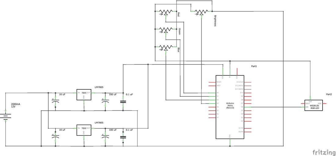
Now, There are multiple ways to convert 12V into 5V. One could simply use resistors and create a voltage divider. The problem would be that the current would drop aswell, and the voltage wouldn't stay consistant as the components heat up (unless you have nice shiny expensive resistors).
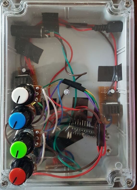
The best way to do it and keep the voltage (accoding to my Dad, and now me) is to use a voltage regulator. Specifically an LM7805 which will regulate the voltage at 5V and allow for 1Amp of current. only 1Amp? thats not enough..... its ok though.. you can place them parallel in the circuit and it will double the current and keep the voltage the same! So thats exaclt what i did, i went and bought some connectors for my 12V power supply's, two LM7805, some capacitors and a pre punched circuit board, and built this! And it works!!!!! (i later added heatsyncs to the LM7805 because they get hot) |
|
one other fun little apsect about this project is that i fitted a 1/4" TRS jack to the end of the lights to send the code and power through.
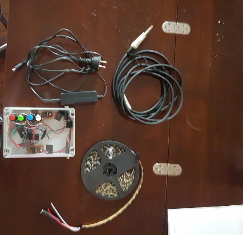
Heres a picture of all the required components for it to work, and a little video of me operating it! enjoy~~
Heres a picture of all the required components for it to work, and a little video of me operating it! enjoy~~
|
|
Star Sheet
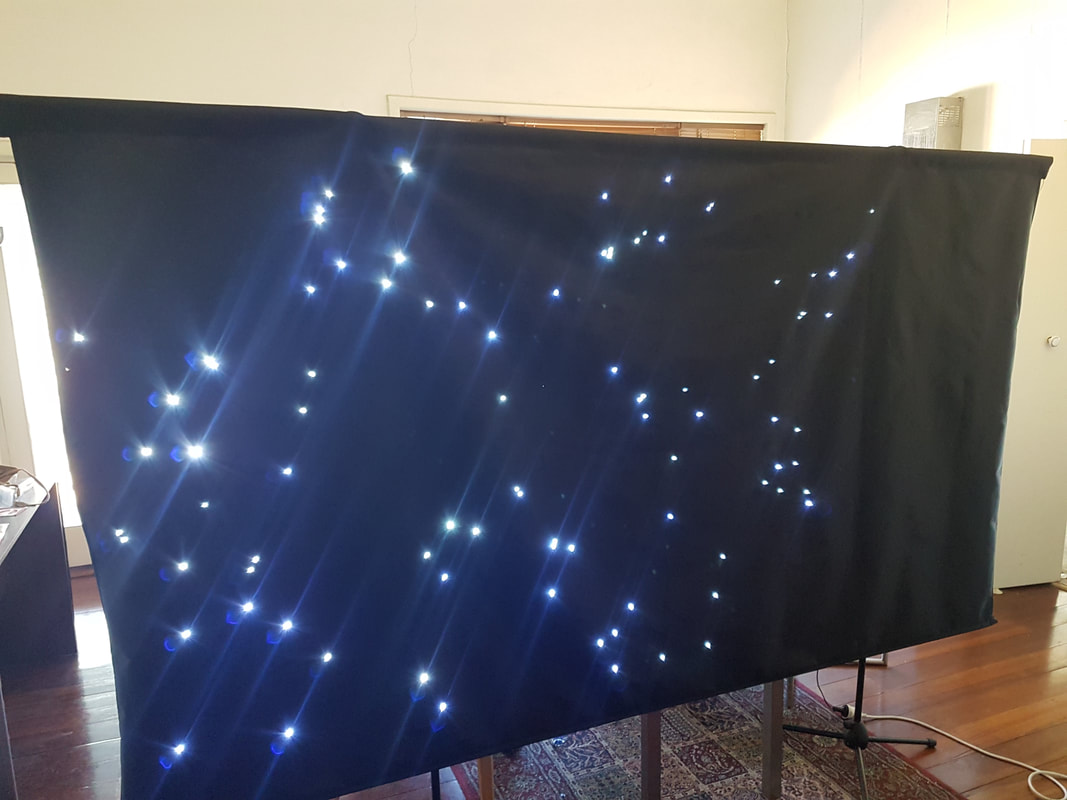
The recital for my third year of composition is going to be taking a space theme, and as such i decided to build myself a star sheet backdrop for my performance.
As you see it in the picture above the star sheet is incomplete, with the final section still missing lights (right hand side). The lights are positioned such that they potray a section of the night sky, including the constilations Capricorn, Aquila, Scutum, Ophiuchus, Serpens, Sagittarius, Scorpius, and will soon include Libra and Lupis. Each constilation is assigned a PWM port on an arduino that has the potential to fade the LED's brightness. This opens up the possibility to assign tracks in ableton to different constilations and they can reflect multiple different tracks the music, but also allows them to twinkle seperately from one another. Because the consilations are all assigned to one pin, the brightness of the whole constilation will be altered which will highlight the patterns that we can look out for in our night sky. My hope is that by the end of the performance, my audience might start to notice these patterns in the night sky and inspire them to look up into space and dream, much like i have at certain points in my life.
This project was also a fantastic prototype for including LED's and lighting to clothing and costumes, which i might be doing at a later stage (if i can eventually figure out how to send Serial data over WIFI or bluetooth for complete control of the system).
If you're interested to read more about the process of getting this build underway, please refer to my research blog!
https://danieljohnohm.weebly.com/research-blog/the-star-sheet-design
https://danieljohnohm.weebly.com/research-blog/the-star-sheet
https://danieljohnohm.weebly.com/research-blog/the-star-sheet-design
https://danieljohnohm.weebly.com/research-blog/the-star-sheet
20 x 15 RGB matrix
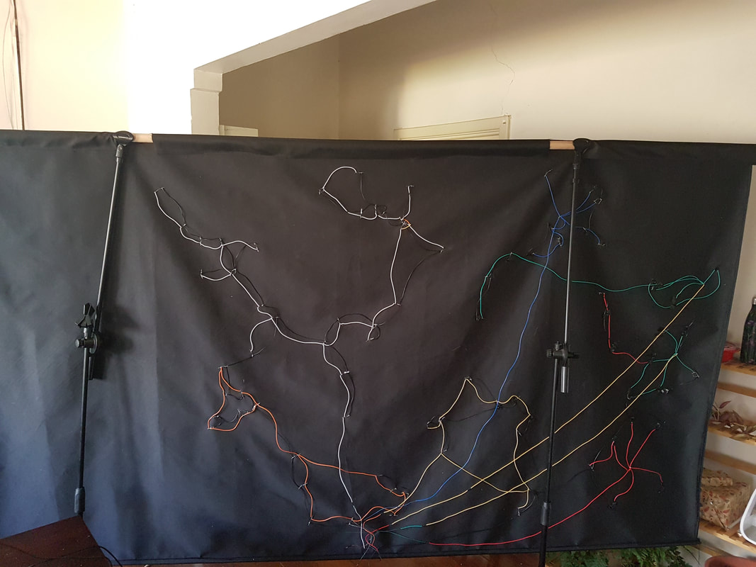
Spider LED: 7.1 surround metering
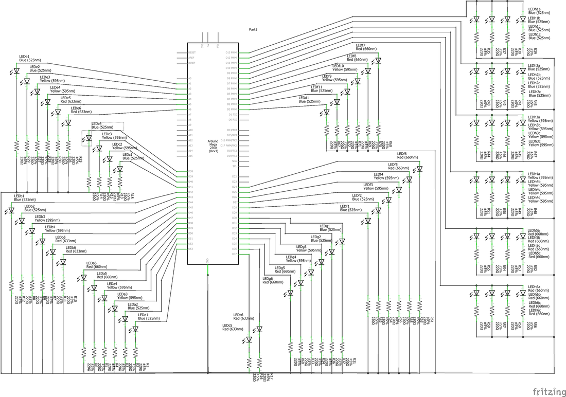
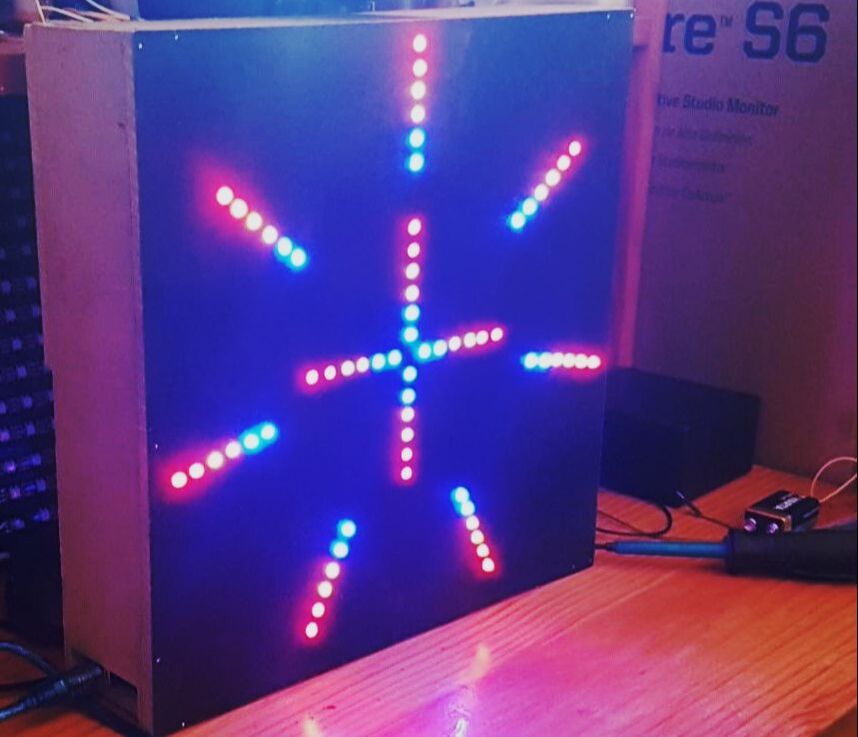
The Spider LED was designed to meter the volume from 8 different sources (perfect for metering 7.1 surround sound) on LED's.
Max/MSP sends metering information to an arduino which allocates an on off position to the different LED's.
This can be used as a tool for monitoring the valume of each speaker, or as a visual display for performance.
Max/MSP sends metering information to an arduino which allocates an on off position to the different LED's.
This can be used as a tool for monitoring the valume of each speaker, or as a visual display for performance.
This project required me to learn basic C++ coding for the arduino, and sending information over a sreial port from max to the arduino chip.
I remember having a lot of issues sending more than one value over the serial port. The information would swap over the lights and i had to find an effective way to "parse" the values over different variables within the code.
I remember having a lot of issues sending more than one value over the serial port. The information would swap over the lights and i had to find an effective way to "parse" the values over different variables within the code.
|
|
I started with just one controlled variable from an audio source, and with just one channel things were working well! The problems came up when i needed to parse two or more seperate variables. The first issue was with my code in the arduino.
i was sending integers from Max/MSP to my serial port, using a code that had a "if Serial.available()" and "Serial.read()" to grab the integers and express them on the lights.
|
Arduino coding solutions
The problem with "Serial.read()" is that it takes all of the information coming through the serial port and assigns it to one variable. This is fine if you have only one stream of information to be expressed but it doesnt work if you have more. I needed to use "Serial.parseInt()" to grab just one of the integers and assign it to one variable. By adding a space between the integers the arduino could recognise that two seperate integers were being sent, and it would assign each integer to a seperate variable. I found through monitoring the serial port and "serial.print"ing the variables there, that this was indeed solving this issue. However it still wasn't working in the way i wanted it to with my lights.
My second problem was that "if Serial.available()" wasn't specific enough. Due to the fast speed that the integers were coming in, the variables would be swaping from one set of lights to the next rather then staying set on their assigned set of lights. I tried different combinations including "if (Serial.available() > 0) and using "Serial.read()", then changing to use "Serial.parseInt()", then finally i discovered that the solution was to define it more specifically. "if (Serial.available() == 2)" fixed this issue. I ran another test with the serial port and things were working like i wanted them to. this section of the code looked like this:
if (Serial.available() == 2){
valuea = Serial.parseInt();
valueb = Serial.parseInt();
}
To translate the language it was like i was saying "if the serial port has two integers in the stream then the first integer gets assigned to one variable and the second goes to the other one." By changing the number after the Serial.available() you can assign any number of integers to be parsed to different variables.
This worked great as long as the information was being entered using the serial monitor on the arduino software, but i was still having issues sending the information with max.
I went back to the online forums, searching high and low for solutions.
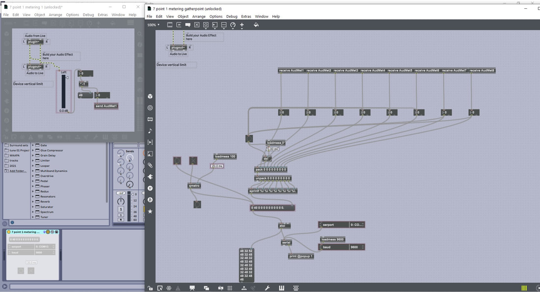
Max/MSP serial solutions
I wasn't immediately aware that if i wanted to send integers from Max/MSP to arduino over the serial port, that i would have to convert those integers to ASCII before i sent that information. This was the first quick fix and it was solved by simply adding a "atoi" object just before i sent the integers to the serial port.
The second quick fix was the means in which i packed and unpacked information to send it to the serial port. In Max/MSP, the pack object will only send information if it receives a change in the first channel, or if it receives a bang in that port. that means if the first channel isnt moving, and the second one is, it wont record the change in the second channel until it receives a bang in the first channel. To fix this issue i simply added a button that would send a bang to the first channel if there was any change in the information in the second channel.
I had finally solved all of the issues inside the arduino code for sending multiple integers and i tested this without using max and was certain it was working, but every time i tried to send information through max, the variables would still swap places with the lights. It took many hours of testing different ideas and figuring out what the solution was. I knew the code in the arduino was working for as long as i was using the serial monitor, but it still wasn't working in max.
While the serial port was open using Max, i couldn't monitor what exactly was being sent through the port using the serial monitor so i used my liquid LCD to monitor what exactly was being sent over the serial port. below there is a video of when i finally solved all of the issues with sending multiple integers over the serial port in Max/MSP.
I tried adding a constant rate for the information by using a qmetro object and a message box. Before, the information would send if there was any change to any integer within the package of integers. information would rush in at points where there was a lot of movement causing the arduino to freeze up and stop working. I figured that by controlling the flow of information, that it would solve the issue of the variables swapping places aswell, but it didn't.
I discovered the solution almost accidently after spending hours looking at forums for arduino codes and max/MSP codes and programs alike, after the frustration of not being able to get it working, and trying many different small alterations to both the arduino code and max patch the solution was simply to add a full stop to the end of the code. The issue was that, due to the fast rate that the integers were coming in from the serial port, the arduino was getting confused where the beginning and end of the code was. By adding a full stop to the end of the code, the arduino could see that the end of the code was defined. With this discovery i realised that i could meter more then just two channels of audio, i coud do as many as i wanted to! (given that i had enough ports on the arduino to do so). With this discovery, everything was finally working perfectly, now all i had to do was build a box and solder in the components.
I discovered the solution almost accidently after spending hours looking at forums for arduino codes and max/MSP codes and programs alike, after the frustration of not being able to get it working, and trying many different small alterations to both the arduino code and max patch the solution was simply to add a full stop to the end of the code. The issue was that, due to the fast rate that the integers were coming in from the serial port, the arduino was getting confused where the beginning and end of the code was. By adding a full stop to the end of the code, the arduino could see that the end of the code was defined. With this discovery i realised that i could meter more then just two channels of audio, i coud do as many as i wanted to! (given that i had enough ports on the arduino to do so). With this discovery, everything was finally working perfectly, now all i had to do was build a box and solder in the components.
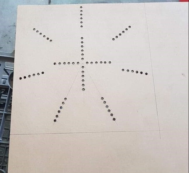
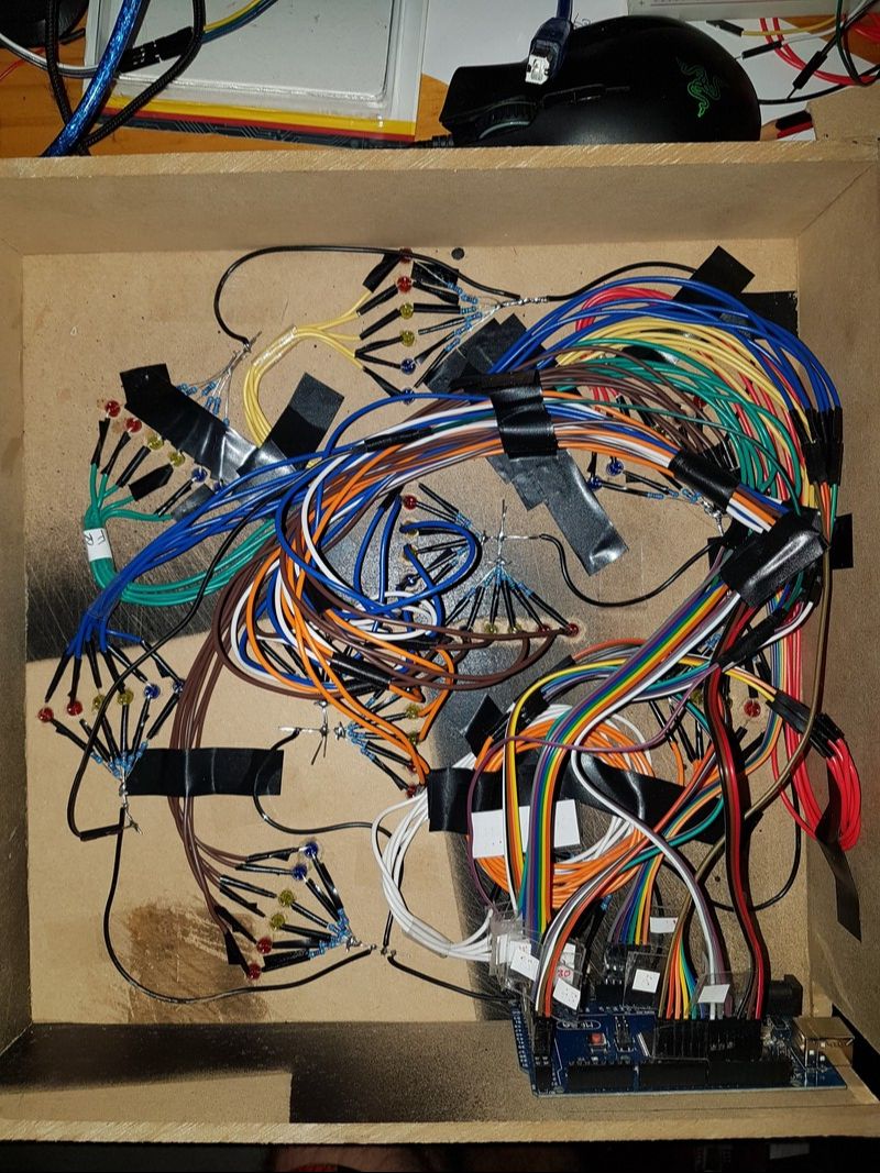
Design
I build the box out of a sheet of MDF. Everything was done manually, i mesured the placements of the holes by using a ruler and a protractor, drilled all the holes using a hand drill, and cut the material to length using a hack saw. Using a lazer cutter would have been a more efficient and accurate way of doing this, but i didnt have one available to me at the time, and i was eager to get this project finished.
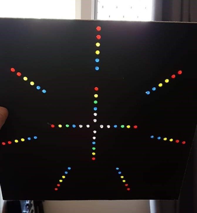
I spray painted the front cover black to make the lights stand out more and placed different coloured LED's in the holes to find a colour scheme that i was happy with.
I cut four more peices of MDF for the sides of the box and nailed and glued them in. by placing my arduino at the bottom i could calculate how much wire i would need to reach the LED's. I soldered the LED's with the required wire length and placed them in the holes to solder the resistors together. This held them together at the right distance from eachother to super glue them into the holes. Each LED has a 220 ohm resistor just before the ground wire. The thickness of the resistors wires prevents the wires from crossing eachother and sho0rting, but i wrapped each soler point with electrical tape for further prevention. In hindsight this was very time consuming, and in future projects i think i'd prefer to use heat shrink to make it more efficient.
The Chimeaphone - Instrument
The chimeaphone is a frame with galvonised steel pipe cut to different lengths, hanging on fishing wire.
The idea was to create a Xylophone type instrument, but with the tambre of wind chimes.
The idea was to create a Xylophone type instrument, but with the tambre of wind chimes.
My inspiration for this instrument started when i made my first set of wind chimes for my mums birthday. I was interested in creating wind chimes with healing affects and had a mild obsession with the 432Hz healing tone.
I started by cutting the pipe into random lengths and testing each one to chart the difference comparison from length and frequency. From there i was able to plot a graph which would give me my rough estimates for length for specific frequencies.
I'd cut the pipe 5mm longer than my estimate, test the frequency and sand the pipe back until it was within 2 Hz of my desired frequency.
